Steam added to stale air is just that, steam added to stale air, it is not löyly
Proper ventilation is critical for a sauna and for löyly – no proper ventilation, no löyly.
Proper ventilation truly gives life to a sauna.
Unfortunately most of the information available in English is inaccurate. It confuses heater cooling and ventilation for humans in electric saunas, and relies on bad or outdated information for both electric and wood. The result is that saunas in North America almost universally have poor ventilation. Wood fired saunas have air for combustion and little or none for ventilation, electric have air to cool the UL mandated but unnecessary heater high-temp sensor but little or none for ventilation for human occupants.
Bad ventilation is likely the number one problem plaguing saunas across the English speaking world and why it’s said that “90% of saunas in North America are bad, and the rest are worse“.
Fortunately proper ventilation is not difficult. In Finland, Sweden, Germany and most of elsewhere a good sauna builder will provide a fresh air supply (typically in the ceiling above the heater), and for electric heated saunas, a mechanical exhaust below the foot bench, it works well and everyone is happy. It’s more confusing, and thus more complicated seeming, in North America.
This is an addendum to Trumpkin’s Notes on Building a Sauna which should be read for further understanding. For further information on measuring temp, humidity and CO2 see ‘Thermometers and Measurements’ in the menu above.
If you want to insure the best possible outcome for your sauna and ventilation then I highly recommend Lassi Liikkanen as a consultant.
Table Of Contents
- TL;DR Summary
- The Need For Ventilation (Wood & Electric)
- Wood vs Electric (Wood & Electric)
- Comparing Ventilation Schemes For Electrically Heated Saunas (Electric)
- More (for those who want to geek out on this topic) (Electric)
- Two Temperature Sensors In North America (Electric)
- Confusion, Controversy and Problems (Electric)
- Proper Ventilation For Electric Heated Saunas (& Wood Fed From Outside)
- Using Ventilation Properly
- Ventilation – Extra Stuff
- Troubleshooting
- Ventilation Options For Wood Burning Heaters (and why Finns are changing it)

Proper Ventilation in a sauna is critical for numerous reasons;
- Maintain healthy CO2 levels.
- Remove unhealthy VOC’s, Pathogens and other gook.
- Remove airborne particulate matter (PM 1.0 & 2.5)
- Removel of steam (so that we can do it again)
- Cooler air that results in hotter stones for better steam.
- Removal of unpleasant odors.
Proper Ventilation for Wood Heated Saunas Fed from Inside the Hot Room:
For Wood Heated Saunas Fed from Inside the Hot Room I think the ideal is three adjustable fresh air supplies; 1) above the heater, 2) below the foot bench on a wall opposite the heater and optionally, 3) near the floor behind/below the heater. This combination of Opt 1 and 2 below will allow for varying adjustments to find the best ventilation for a particular sauna in a particular environment on a particular day. It will give us the best of both.
Opt 1 (Downdraft)**:
- Fresh Air Supply For Bather Ventilation Above The Heater – This is what provides fresh air for bathers and more importantly for removing CO2, excess humidity and other contaminants. This should be located above the heater; 1) On the wall above a point halfway between the top of the stones and the ceiling, nearer the ceiling is best, or 2) In the ceiling directly above the heater. This should be adjustable, ideally come from outside and include a back flow device. A bit of updraft duct works well for back flow reduction as it also reduces static pressure.
- Air Supply For Heater Combustion Near The Floor – This provides excess combustion air for the fire and should be adjustable. Typically placed under the benches though can be almost anywhere near the floor.
- Natural Exhaust In Opposite Corner Near Or In Ceiling – This is opened after the day is done to allow excess moisture to be exhausted and is usually located near a corner furthest from the heater.
Opt 2 (Circulating)**:
- Fresh Air Supply Below The Benches Opposite The Heater – These provide combustion air and hopefully good ventilation for bathers. This is Lassi Liikkanen’s improved version of the traditional ventilation used in wood heated saunas in Finland. By moving the fresh air supplies to the opposite side of the space there is better potential for mixing to provide better ventilation for bathers. Two to Four supply vents located under the benches, possibly on two adjacent walls to account for changing wind conditions.
- Natural Exhaust In Opposite Corner Near Or In Ceiling – This is opened after the day is done to allow excess moisture to be exhausted and is usually located near a corner furthest from the heater.
Proper Ventilation for Electric Heated Saunas and Wood Heated Saunas Fed from Outside the Hot Room (Mechanical Downdraft):
- Fresh Air Supply For Bather Ventilation Above The Heater – This is what provides fresh air for bathers and more importantly for removing CO2, excess humidity and other contaminants. This should be located above the heater; 1) On the wall above a point halfway between the top of the stones and the ceiling, nearer the ceiling is best, or 2) In the ceiling directly above the heater. This should be adjustable, ideally come from outside and include a back flow device. Incorporating a bit of updraft duct and/or a mechanical blower may be recommended. For saunas larger than about 20-24 m³ this should likely be mechanical.
- Air Supply For Cooling the Heater High-Temp Sensor Behind/Below The Heater (UL Heaters Only) – For heaters that have this sensor (typically all that are UL Listed) this provides air to cool the sensor to prevent the high-temp limiter from nuisance tripping. This should be adjustable and only just enough air flow to keep the sensor from tripping. Note: If UL update UL 875 to conform to EU standards then this supply will no longer be necessary.
- Mechanical Exhaust Below The Foot Bench – And likely also below the top of the stones. This s/b about 20-25 CFM per person plus 15-25 CFM for the heater HT sensor (so 100-125 CFM for a 4 person sauna). An inline duct blower such as from Fantech is usually the best option. This must be located below the foot bench, not above.
- Natural Exhaust In Opposite Corner Near Or In Ceiling (Optional / Not Needed) – This is opened after the day is done to allow excess moisture to be exhausted and is usually located near a corner furthest from the heater. Alternatively, leave the exhaust blower running for an hour or two which will do a better job of clearing moisture. Note: We’ve had Mechanical Downdraft in our sauna for 4 years (since 2020) and have found no need for this exhaust. Running the blower for a couple of hours is more than sufficient.
* Note 1: Natural ventilation does not work well in electrically heated saunas. It results in increased stratification, increased CO2 levels and limited exhausting of steam which all lessen the sauna experience. Electric heated saunas should always have mechanical downdraft ventilation if at all possible.
** Note 2: The above may not apply to heavy steel stoves such as Kuuma or older Nippa that do not produce a good convective loop. A good convective loop is critical for ventilation to work well.
Note 3: Ventilation in a sauna is designed for normal levels of CO2, bacteria and other gook. Excessive movement such as exercising or yoga can produce greater amounts of CO2 (≈8x vs someone sitting still?) and levels beyond what standard ventilation can effectively exhaust. Similarly, high bacteria levels from someone not showering/rinsing well before entering or wearing textiles beyond a minimal clean swimsuit can be greater than normal ventilation is designed to handle.
Head to Toes Temp Difference – A key goal of sauna is to be heated evenly head to toes and this is a primary element behind the saying ‘Feet Above The Stones’. We ideally want no more than about a 15-20% head to toes temp difference and any more than 27% is generally deemed unacceptable. In electrically heated saunas (and wood heated fed from outside the steam room) natural convection results in an INCREASE of about 8-12°c while mechanical downdraft with exhaust below the foot bench results in a DECREASE of about 4-15°c. This is one key reason why Mechanical Downdraft is so strongly recommended.
For example, in our sauna, natural convection results in a head to toes temp difference of about 32% which is rather bad. Mechanical downdraft results in a difference of about 16°c which is ideal.
Continue reading for why ventilation is so critical, why the above is the recommended ventilation used in Finland and elsewhere and more detail on the above. If you just want to get to it then skip down to Proper Ventilation For North American Saunas.
Reducing Fire Hazards – Fire is a hazard in all saunas and something that must be considered in the design and building of a sauna. As well, wood surfaces should be monitored for signs of pyrolysis. The ceiling above the heater in a sauna is a key area that can overheat and combust resulting in a fire. Bringing fresh cool air in above the heater (downdraft ventilation) either in the ceiling or high on the wall near the ceiling may help to keep this area cooler and reduce the risk of fire.
Important Note (Jan 2024): UL are expected to update UL 875 to conform to EU standards in the coming months. This is VERY GOOD NEWS. This will eliminate a lot of confusion in North America. This should eliminate the need for an air supply behind/below the heater to cool the overly sensitive high limit sensor, allow proper placement of the thermostat sensor over the sitting bench and allow for temps higher than 90°c. Overall this will be a big improvement for North American sauna users and builders. More to come…
Important Note (Jul 2025): UL have largely adopted IEC standards for electric sauna heaters. I will provide updates on this over the coming months here: https://medium.com/@trumpkin

Ventilation is about breathing and in a sauna this is critical, even more so than in our homes or offices. One or a bunch of people closed up in a tiny room like a sauna quickly results in very high levels of exhaled CO2 that is unhealthy, harms the sauna experience and must be removed. Removal of excess CO2 is the primary purpose of ventilation.
Post workout sauna in a sauna with poor ventilation may actually do more harm than good due to the resulting high blood pCO2 that may reduce rather than enhance recovery.
Removal of various other odors, VOC’s and pathogens is important as well. Flatulance is normal, but not something we want hanging around. If someone has a developing Flu or Covid we want the pathogens they exhale to be removed as quickly and effectively as possible. As of Feb 2023, Covid is still a concern and one of the best ways to know if an occupied space has proper ventilation is to measure CO2 to insure that it’s at least under 700 ppm and ideally below 550 ppm.
When we throw water on the stones to create steam we also create particulate matter – PM1.0, PM2.5 and PM10. I’ve measured this in my and one other sauna and presume it happens in many others if not all. My guess is that this is mostly bits of the stones but likely also includes some of the steel from calrod heating elements or iron from wood heaters. It’s important that this PM be removed fairly quickly as breathing it is quite unhealthy. (Note: We know from studies that the health benefits of sauna outweigh the brief exposure to PM when this PM is removed quickly. That may not be the case if the PM is not removed quickly.)
The air movement provided by proper ventilation also helps to eliminate problems of windows fogging.
Lassi Liikkanen points out in “Secrets Of Finnish Sauna Design” that ventilation is necessary also for removing excess humidity during sauna or else successive throws of water on the stones will, over time, result in too much humidity. In his book ‘Finnish Sauna’ Allan Konya similarly talked about the importance of good ventilation for controlling humidity, pointing out that just as we want cycles of hot/cold/hot/cold we also want cycles of humid/dry/humid/dry. After throwing water on the stones we then want that humidity removed so that overall humidity goes back down to where it was before so that each successive throw results in the same level of humidity increase and same comfortable effect. Allan’s book was published in English 35 years ago – the need for good ventilation is not new.
Cooler air also insures that the elements on an electric heater turn on frequently enough to keep the stones sufficiently hot to produce good steam. Without this cooling air the sauna can remain quite hot so the heater does not turn on frequently enough.
Note: If a sauna will be used for hot yoga or any other activities then ventilation needs increase significantly. Being physically active in a sauna can generate about 8x as much CO2 as sitting quietly. This does not require 8x the ventilation rate however but about 2x. So 20-30 l/s (40-60 CFM) per active person.
So there are numerous elements critical to a good sauna experience that rely on proper ventilation.
Note that the door opening does not provide ventilation. If it did then you would also replace all of your heat with cooler outside air. Without good ventilation, however much heat there is in our sauna is how much CO2, Pathogens and other stuff there is.
Disclaimer: I am not an engineer nor doctor. Nor any kind of expert on sauna. The following is simply a bunch of notes on what we learned building our sauna and that we wish we’d known much sooner. Use at your own risk. I strongly encourage everyone reading this to do further research on all of these topics and in particular to read Lassi’s book (listed at the end). And if there is anything inaccurate below please let me know so that it can be corrected.
For more on why proper ventilation is so important: Ventilation – Finding Good Pure Air.

All saunas need ventilation for human occupants (bathers); to remove CO2, excess humidity and other undesirable stuff in the air and replace it with fresh clean air.
The difference is how exhaust is accomplished. Wood burning heaters often act as a powered exhaust. They can produce anywhere from 10 to 600 CFM of exhaust airflow to pull stale air (CO2, humidity) out. This then creates low pressure that in turn pulls fresh air in through fresh air supply vents.
An electric heater does not do that nor does a wood burner that is fed from and receives combustion air from outside of the sauna hot room. So these saunas need a mechanical exhaust blower to exhaust the stale air.
Much of the following focuses on the latter but many of the concepts discussed also apply to wood burning heaters fed from inside the sauna. Towards the end is a section specific to wood burning.

This applies as well to wood burning saunas that are fed from and receive combustion air from outside of the sauna hot room.
Heater Cooling vs Ventilation
Supply air entering below the heater or behind the heater is for heater cooling in North America and elsewhere that follows similar UL guidelines. This DOES NOT provide ventilation.
For reliable ventilation in a sauna with an electric heater the fresh supply air should enter ABOVE the heater and exhaust should be powered mechanical exhaust (ideally from below the foot bench on the wall opposite the heater – more below).
Three Schemes
There are three psuedo-viable schemes for ventilation in electrically heated saunas;
- Natural (Convection) Updraft – Fresh supply air entering below the heater (or sometimes below the door or behind the heater) with exhaust in the ceiling or, as recommended by Tylö-Helo in the U.S., 24” above the floor on the opposite wall. This is the predominant system used in the U.S. and North America, is recommended by Tylö-Helo and other manufacturers for their North American heaters and is what online searches in English usually turn up.
- Mechanical Updraft – Same as above but mechanical (typically an electric duct blower) for the exhaust instead of relying on natural convection.
- Mechanical Downdraft – Fresh supply air entering above the heater and mechanical exhaust from below the foot bench (typically an inline duct blower). This is the system used by better builders in Finland.
The problem is that neither #1 nor #2 work. Neither provides good ventilation nor even any ventilation at all. Physics says that they will not work and studies by VTT in Finland prove that they don’t work*. Research I’ve done in our and other saunas support this and indicate that both of these result in high, unhealthy and uncomfortable levels of CO2 which is why people so often complain about stuffiness, feeling dizzy or sudden anxiety in North American saunas. These also increase stratification and ‘cold feet’.
Mechanical Downdraft, #3, does provide good ventilation. Physics says that it should and studies by VTT say that it indeed does. In our and other saunas it results in proper low levels of CO2, lower PM, proper levels of moisture, less heat stratification – and a much better sauna experience.
To give you an idea of how much of a difference this makes. Here we were first in a sauna using Mechanical Downdraft. You can see that CO2 maxed out at about 700 ppm which is good. At 4:30 we moved to a sauna with natural convection. CO2 levels here were much higher and this was also very noticeable in our experience – a bit more difficult to breath, less comfortable and even though a lower temp we couldn’t stay in as long.

Understandably, sauna builders I’ve talked to in Finland and Sweden say to use mechanical downdraft. VTT has recommended mechanical downdraft since their research in 1992 showed it the best and realistically only good option. Tylö-Helo and other heater manufacturers recommend mechanical downdraft outside of North America and online searches in Finnish, Swedish and German show it as the recommended solution.
There are good reasons for this.
1 – Cold Air Sinks. Cold air entering below or behind a heater does not flow up in to the heater as many people wish. A little flows up in to the heater, a little more rises up to envelope bathers feet in cold air, but the majority flows across the floor and then out the exhaust without providing any benefit.

On the other hand, fresh air entering above the heater will get entrained in the upward rising heat and convective loop, disperse throughout the sauna along with that heat and then exit taking CO2 with it.
This chart (below) from the 1992 VTT study sums it up well. T1 and T2, which are the recommendations of North American heater manufacturers, simply flow down and across the floor. They provide cooling for the heater but no ventilation for bathers. T3 partially works but not well as a lot of the cold air blows around and through the rising hot air rather than getting entrained in it. In the case of a floor standing heater sitting a few inches away from the wall a portion of the cold air will also flow down to the floor behind the heater, and actually this will be the case for any vent that is not above where the heat plume expansion meets the wall.
T4 is the only supply solution that results in proper ventilation for occupants. There are two reasons for this; 1) It is above where the rising plume has spread out and meets the wall and 2) is high enough that the colder air that begins to sink down will be more likely to get entrained in the rising plume.

2 – Natural Convection Is Unreliable. Any kind of natural convection in an electrically heated sauna is unreliable and rarely if ever results in enough air flow for a healthy environment and sometimes zero airflow. In a wood fire heated sauna the heater itself provides sufficient exhaust airflow but electric heated saunas (and wood fire saunas with external combustion air) need a blower to sufficiently and reliably exhaust stale air.
Natural ventilation is romantic but it only works with wood heaters that pull combustion air from within the sauna hot room. Stale air is not romantic.
3 – Updraft Is Undesirable. Any Updraft Ventilation, natural convection or mechanical, that pulls cooler air upwards results in lower temps for the foot bench. The most critical problem here is that foot benches in these saunas then do not maintain high enough temperatures (minimum +55°c / +130°f but ideally +62°c / +149°f) to kill bacteria and mold. And, while not as important as maintaining healthy CO2 levels or killing bacteria, this also results in cold feet and legs which is quite uncomfortable.

Updraft interferes with the convective loop that creates the löyly cavity. This increases stratification which we don’t want and also reduces or sometimes totally eliminates steam (the final element of löyly) reaching bathers. We want steam to follow the convective loop; rise above the heater, flow across the ceiling and then down on us fully enveloping us from head to toe. An updraft is flowing against this and just carries the steam out of the upper vent.
Since our mouths and noses are up high, Updraft ventilation is also pulling whatever is down below up for us to breath. That’s not very pleasant.
Downdraft Ventilation (below) that works with the convective loop pulls warmer air downward, does a better job of removing exhaled CO2, is much more likely to maintain the temperatures needed for killing bacteria and mold on foot benches, is providing cleaner and fresher air directly to bathers, results in warmer and more comfortable legs and feet and enhances rather than reduces the steam that’s so critical to löyly.

This is why heater manufacturers and sauna builders in Finland, Sweden, Germany and elsewhere recommend that the fresh air supply be from above the heater.


4 – Ceiling or High Wall Exhausts Kill Löyly – An exhaust in the ceiling (or really anywhere above the foot bench) exhausts steam and heat, quickly killing any löyly before bathers can enjoy it. A high exhaust vent is good for clearing humidity after the days’ session is done, not good for use during sauna.

It’s important to understand that there are two different temperature sensors in North American saunas with electric heaters; A Thermostat Sensor for room temp and a High-Temp Sensor (or High Limit or HL or HT or Thermal Safety or Overheat Protection or Overtemp protection).
Thermostat Sensor – The first is the thermostat that controls the overall temperature of the sauna. In North America the thermostat sensor is often mounted on the wall somewhere above the heater. UL states that the temp in a sauna cannot go above 90°c or 194°f. The Thermostat Control is typically mounted on the wall outside of the sauna or on the face of the heater – it is how you adjust the desired temperature. It uses the Thermostat Sensor to know what the sauna temp is and then turns the heater on/off as needed to stay close to the desired temp.
High-Temp Sensor – This is typically mounted on or inside the electric heater. When this senses heat levels above its set point (about 350°f on our Himalaya) it will trip the HL Switch (High Limit Switch or Overheat Protection Switch or Thermal Protection Switch) and shut off the heater. This requires waiting until the HL Sensor cools below the set point and then resetting the HL Switch (usually a button near the bottom of the heater). This is the sensor that most often causes tripping problems for electric heaters in North America. This sensor is a UL requirement for North America and is not present on heaters in Finland, Sweden or elsewhere.

Given the overwhelming benefits of Mechanical Downdraft Ventilation (#3) and the critical drawbacks of the other two, why would anyone recommend #1 or #2?
And, why do Tylö-Helo, Harvia and others recommend Mechanical Downdraft everywhere but North America? Last I checked physics is the same in North America as in Finland.
The reason for their recommending supply air below the heater instead of above is to provide cooling for the heater itself – for the High Temp Sensor. The cooler air from a vent behind or below the heater is needed to cool the HT sensor as otherwise it will trip prematurely and shut off the heater until it cools down below the set point.
Heaters sold outside of North America do not need a lower vent to cool the heater or HT sensor nor do they have problems with these tripping unnecessarily. Importantly, electrically heated saunas outside of North America also get much hotter than those in North America (because of UL restrictions in North America) so if anything they should have a greater need for this lower vent yet they do not have one.
There is clearly a major difference in heaters sold in the U.S. and those sold in Europe and it’s a difference that is a significant disadvantage to U.S. consumers and our health.
That I can think of there are only two reasons for the High Limit switch to trip at such a low temperature for U.S. heaters; 1) A UL requirement or 2) Low quality manufacturing. Both are reasonable.
Underwriters Labs, UL, does a lot of good and their recommendations, at least on the surface, result in a safer world for all of us. We do know that they require a very low overall sauna temp of 90°c (or actually well below this) for electric heaters so it is not unreasonable to assume that they also have other regulations that result in manufacturers including the high limit or overheat protection switches that are causing our ventilation (and other) problems**.
U.S. consumers have a reputation for prioritizing lower cost over better quality and of not demanding higher quality – throwing the baby out with the bath water. This would not be the first time that lower quality products are sold to U.S. consumers vs those sold elsewhere. Lower quality have a lower manufacturing cost that results in higher profits. Lower quality also results in shorter life-spans and so higher sales of replacement products. What’s not to like – for vendors. A lower temp setting on the HL Sensor in heaters sold in North America will also reduce warranty liability and the costs associated with that which also helps profits.
I have not yet been able to verify either of these. In my discussions with UL I have yet to see anything from them that would require the low HL switch temp. Heater manufacturers insist that those sold in the U.S. are the same quality and often the exact same heaters as those sold in Finland and Europe (except for anything needed to meet local code requirements). Yet, there is a very clear difference.
To summarize, it appears that the very low set temp for the High Limit switch causes a need for supply air to cool the heater or HL sensor. Manufacturers then chose a solution in North America to provide this cooling to the heater rather than provide ventilation to occupants. This results in high levels of CO2 and other problems for North American saunas.
Another problem is that people, understandably, find workarounds to these UL restrictions to eliminate nuisance trips of the HL sensor and so that their sauna’s can get to the same temps as sauna’s elsewhere.
1) Very often people locate the thermostat sensor much lower than head height so that when the thermostat reads 194°f the actual temp at head height is perhaps 224°c.
This is risky if someone thinks that they’re getting in a 194°f sauna but are getting in a much hotter sauna instead.
There is a similar problem in that the placement required by UL results in actual sauna temps much lower than indicated so an American who thinks they like 190°f (based on a thermostat sensor placed according to UL regs) are actually in a 170°f sauna and are then surprised at what an actual 190°f sauna is.
Finally, temps vary less at lower levels in the sauna so a thermostat sensor placed lower results in greater variability at head height and can result in extremely high temps.
2) People will also often move the HL sensor away from the heater so that it stops tripping. If this sensor is indeed needed rather than only a spurious UL requirement then this increases risk.
Ultimate Solution
We need to be able to use the same ventilation as Finland and others with fresh air entering above the heater and uncomplicated by the need to also cool the heater or HT switch. This will likely require either changes from UL, changes by manufacturers or both to eliminate the need for cooling the heater or HT sensor. This is being worked on so hopefully we’ll have better options soon. (Jan 2024 Note – Changes from UL to align better with international standards appear to be nearing completion.)

Note: For saunas that do not have a UL mandated high temp sensor with a very low trip point the lower supply vent can be ignored.
Note for North America: Until we have heaters without overly sensitive high-temp sensors and can do the same ventilation as others we need to make some compromises with a bit of a hybrid approach. The following applies to electrically heated saunas and most wood heated saunas that are loaded and receive combustion air from outside of the sauna hot room (typically the changing room). Wood heated saunas with loading and combustion from within the hot room have some slightly different criteria discussed further down.
Natural Convection Doesn’t Work Well – If you have an electrically heated sauna you realistically need mechanical exhaust using an electrically powered duct blower or similar. Combustion in wood heaters provides exhaust for wood burning saunas, electric heaters do not. Natural convection requires Updraft ventilation and so comes with the problems of that we discussed above.
That said, you can certainly still do natural updraft if you desire. Thousands of saunas in Finland built prior to the 1990’s were done this way and they are still reasonably good saunas. Just not as good as more recent builds that use mechanical downdraft ventilation and so have fresher air and less uncomfortable stratification.
10-12 liters/sec (20-25 CFM) Per Person – We want to keep CO2 levels for bathers below 700 ppm and ideally below 550 ppm. Or not more than 150-300 ppm above outside ambient CO2 (typically 420 ppm). A general recommendation is a minimum of 10 l/s (30 m³ / hr, 20 CFM) per person (DIN1946 says that18 CFM are needed but that is in a larger space with lower cardio activity). Due to higher levels of CO2 in exhaled breath of active people however gyms often require 20-30 CFM per person and sauna’s similarly need somewhat more. How much more needs more study. Initial measurements in our sauna and others show a need for somewhere between 10 and 12 l/s per person to keep CO2 levels appropriately healthy.
It’s important to note that too much ventilation can lessen löyly by removing too much heat and moisture so the amount of ventilation may need careful balancing.
In North America you need some additional airflow (15 CFM?) through the lower supply vent for cooling the high temp sensor (except possibly for those who’ve moved it away from the heater).
Minimum 6 Changes Per Hour – 6 changes per hour is a good minimum to not go below. In our sauna for instance this is 38 l/s so for one, two or three people we’ll use 38 l/s but for four bathers we’ll use 48 l/s and 60 l/s for five people and so forth.
Lower Rates To Allow For Longer Steam Decay – Many people in Germany and nearby countries (Continental Sauna Tradition) prefer a less dense steam that hangs around longer which can be accomplished with lower ventilation rates. This can result in higher CO2 levels however, though this can be ameliorated with greater sauna room volume per person. FWIW, the German Sauna Federation recommends 10-20 volume changes per hour in public saunas to maintain healthy air quality. Note though that these often have very considerable volume per person.
Similarly, some people like a more humid sauna experience overall vs the very dry / very humid Finnish style. Using lower ventilation rates can help to achieve this.
Higher Rates To Emulate A Finnish Wood Burning Sauna – A higher ventilation rate with Mechanical Downdraft can sometimes help to better emulate the stronger convective loop of a Finnish wood burning stove. This does require a heater with sufficient power to overcome the amount of cooler air being introduced.
Fresh Air Supply ABOVE The Heater – Air for ventilation needs to enter in a way that it sufficiently mixes with the hot air and circulates to bathers faces.
In a well sealed sauna a passive fresh air supply vent with a baffle above the heater/stones, at least 2/3 to 3/4 of the distance from the top of the stones to the ceiling, will usually work well. Without a baffle it can or should be placed near the ceiling. With UL heaters this supply may need to be adjustable to insure adequate air to cool the HT sensor.
This supply can also be located in the ceiling above the heater. If so then cheated slightly towards bathers might be good. This can be placed behind a steel heat shield if there is a sufficient gap, like 75-100mm (3-4”), between the ceiling and heat shield. It may be a good idea to partially close off this gap on the sides away from benches to insure that fresh air flows towards bathers.
Total opening for this for a 4 person sauna should be about 25 square inches (approx 6” round) but it need not be a single round or rectangular vent. It can be a decorative pattern so long as it has enough opening for air to flow through and aligns with the rising plume from the heater. Similarly, a baffle out in front of it can be decorative and have decorative openings so long as the result is the fresh air mixing with the rising plume and not blowing through it or to the sides of it.
Examples:

Lower static pressure for passive supplies is critical to good functioning so a larger vent, like 7” or 8” instead of 6″, reducing the number and degree of elbows and insuring greater openness in grills are all beneficial.
To lessen static pressure and prevent this from back flowing, such as when the door is opened, you should include an updraft duct (Below) – have the supply duct run upwards to the vent for a bit. Hot air rises so it is then less likely to back flow downward in the duct.

A backdraft damper can also help either alone or in combination with an updraft duct though a damper alone will not help with reducing static pressure. A good source for these is Tamarack.
In some cases such as a sauna that is not sealed well or larger saunas where the door is frequently opened this may require a mechanical blower to work well. This blower should match the exhaust blower and provide the same airflow (typically run at the same speed) so that it provides balanced ventilation. One additional advantage here is that the fan curve for both blowers is then less important so less expensive blowers can be used successfully.
This can also be in the ceiling above the heater. If you do this then you should install some form of back flow to prevent this from becoming an exhaust when the mechanical blower is not running (during heat up, etc.).
Heater Cooling Supply Behind Or Below The Heater – A secondary passive supply may be needed to cool the heater or HT sensor for electric heaters. The required UL set point for these is too low for the heater to function properly so it is necessary to have some cooler air on it to allow the heater to continue working.
We want as much of the fresh supply air entering the sauna as possible to provide ventilation and so come from the supply above the heater. So, this lower vent should be adjustable so that only what air is needed to provide cooling of the heater or HL sensor comes from this supply while the rest comes from the upper supply to provide ventilation. In some cases it may be necessary to adjust the upper supply vent to achieve enough cooling of the heater. My guess is that in most cases about 20% to the heater and 80% from the vent above the heater for ventilation will work best.
Placement of this can be tricky. The airflow needs to cool the HT sensor. On the other hand, we don’t want a bunch of this colder air just flowing across the floor which it will naturally want to do. If the heater manufacturer recommends behind the heater then all should be good. If the mfr recommends below the heater then cheating this supply up a bit and perhaps so that the middle of this vent is at the bottom of the heater might help to insure cooling of the HT sensor with as little cold air on the floor as possible.
I want to again point out that this heater cooling supply and all of the complications that come with it are not needed in Finland or elsewhere outside of North America. This appears to be strictly an unecessary UL requirement in North America.
Mechanical Exhaust Below The Foot Bench – This exhaust vent should usually be on the wall opposite the heater, under the foot bench and below the top of the stones. This will help to pull warmer air down past bathers feet and result in a much more comfortable experience. Generally placed in about the middle of the longest bench run but perhaps cheated a bit away from the heater for more even distribution.
Note that for best mixing you want to pull air through the sauna with passive supply vents and a mechanical exhaust, NOT push air in to the sauna with mechanical supply and passive exhaust.
FWIW, we used a Fantech FG-6 #40406 (260 CFM @ 0.2” wc) controlled by a Control4 variable speed motor controller. Set at 67% results in 161 CFM for our sauna given the static pressure in the supply and exhaust ducts and works well for a full house of 6 people. For a single person 25% results in about 30 CFM. Note that this blower is NOT rated for sauna temps. This fan can emit a hum at low speeds with the Fantech controller. A FG6MEC fan and EC-10V controller will not and is a better solution (thanks to kovibalu on Reddit for this info).
Note: AC Infinity do not publish fan curves and in practice have often not worked well. A little bit of static pressure kills their performance. I recommend avoiding them in most cases.
Do not place the exhaust vent above the foot bench (the P2 location from the VTT study). This results in:
- Increased stratification and cold feet.
- Pulls colder and drier air up around feet & legs.
- Disrupts the convective loop.
- Greater energy use.
- Potentially a burned out blower as the air temps at this location are greater than from below the foot bench.

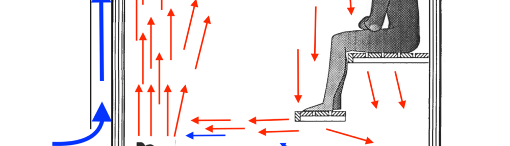
The image below shows what happens around the exhaust vent as it’s pulling hotter air down and colder air up. If this is above your foot bench then that colder air is being pulled up around your feet and legs. Brrrrr!
 Exhaust vent in a sauna showing how it pulls colder air upward. Image courtesy of boxohm on Reddit
Here’s a comparison from a sauna where it was possible to do both. Exhaust from the P2 location (P2 On) pulls cooler air up and decreases foot temps (green line) by about 3-5°c. On the other hand, P1 (P1 On) pulls warmer air downward and increases foot temps and lower leg temps (purple line) by about 3°c. So P2 (above the foot bench but below the sitting bench) increases stratification while P1 (below the foot bench) decreases stratification.
This is actually kind of a fascinating bit of fluid and thermo dynamics. It’s easier to pull cooler air upwards than to pull warmer air downwards. The lower in height of the average of air supplies (not the neutral pressure plane though) and the cooler the fresh air supply the greater the difference is likely to be. The better sealed from outside leaks and lower the exhaust airflow rate the less the difference is likely to be.
Alternate: Mechanical Exhaust From Adjacent Shower Room – If the adjacent commons/changing/shower has good exhaust then it’s possible to allow exhaust from under the sauna door. This was common in Finland during the latter part of the 20th century and according to Lassi generally works OK.
There are some drawbacks to this though. It can increase the heat and humidity in the commons/changing/shower area. If another door or window is left open in the changing/shower then there may not be sufficient draw to clear the air in the sauna. It can short circuit resulting in poor removal of CO2. It doesn’t tend to help with reducing stratification and cold feet as well as exhaust from below the foot bench.
No Leaks – Ideally you want air to enter only through the supply vents so that the air does what we want; provide ventilation for bathers, remove steam and cool the overtemp sensor. So, no gap under the door (or as little gap as is practicable) or other openings where air can come in. This includes the floor. Some very minor leaks shouldn’t be a problem but larger could be. If the sauna will be leaky then mechanical supply (balanced ventilation) will be necessary.
Fresh Supply Air From Outside – Air from indoors will often have high levels of CO2 and other contaminants, this particularly in U.S. homes. We are already stressing our bodies with heat so we want as fresh of air as possible with as low of CO2 and other contaminants as we can get. In most cases air from outside is best. It’s important that this be placed away from any exhausts on the exterior as you don’t want to pull in the same stale air that’s being exhausted.
Exhaust To Outside. Similarly, it is best to exhaust sauna air to outside as exhausting to inside of a home can result in too high of humidity leading to mold growth. It may sometimes be OK to exhaust to a bathroom that has its own exhaust fan to outside. In this latter case it’s preferable to have the bathroom exhaust interlocked with the sauna exhaust to make sure that it always runs when needed.
Measuring – Knowing where to set a rotary knob or programmed HA system for how much ventilation is important as is knowing how well ventilation is working. A Testo anemometer is a good way to do this. Optionally, making friends with an HVAC tech who can do it for you (and knows how to do it correctly). Measurements should be taken on the outside of the sauna for best results. Ideally the inflows to supplies should equal the outflow from exhaust though often inflows will be a bit less as some air will enter elsewhere.
5 Effective CFM is better than 20 Ineffective CFM – If your heater has difficulty keeping up with cold fresh supply air then reduce the flow rather than move the vent lower. 5 CFM entering above the heater that helps to reduce CO2 is much more beneficial than 20 CFM entering below the heater that does not reduce CO2 levels and adds to cold feet.
Clearing Exhaust In/Near Ceiling? – (Maybe) Include a clearing exhaust in or near the ceiling opposite from the heater and supply air. After the day is done this exhaust can be opened (with the heater still heating) with the blower running for about 15 minutes to clear the sauna of accumulated moisture which will help with keeping mold and bacteria at bay. HOWEVER, I’m not sure that this extra vent is necessary. If you have a supply vent over the heater and mechanical exhaust on the opposite side below the foot bench then when you’re done with your sauna for the day you may be able to simply leave it going (heat and ventilation) for 15-30 minutes and get the same result. It should effectively exhaust excess moisture and, assuming at least 55°c at the foot bench, kill most bacteria and mold. This needs more study.
Update: With the upper passive exhaust vent it takes about 1 – 2 days, depending on outside temp/humidity, for our sauna to return to normal humidity after a session. Without the upper vent and using only the mechanical exhaust vent below the foot bench it takes about 1-2 hrs. From an energy cost standpoint it costs about $0.01 (1 cent) to run the blower for that extra time. Easy decision for me. Note that with either, if you will not be using your sauna for a while, it’d be a good idea to keep it at temp (foot bench at least 55-65°c) for at least a couple of hrs (or heat it up the next day) until the humidity has fallen so that the heat can kill any latent bacteria and mold that might want to settle in while it’s not in use.
Duct Size/Design – The smaller the duct the more static pressure and the more noise from airflow – so larger is generally better. Round duct is more efficient than rectangular so always upsize rectangular duct. Here are a couple of charts for duct sizing for passive ventilation. Face is the total vent opening in square inches.

TLDR; A typical residential sauna should usually be 6” rigid duct for passive supply and mechanical exhaust.
If you want to be exact… Every bend, jog, exterior cap, or interior baffle increases the static pressure (resistance to airflow) of the duct which reduces airflow. Smaller duct has greater static pressure than larger duct. So using larger duct and minimizing bends or other deviations can help with airflow and noise.
For reference 10’ of 6” duct @ 125 CFM is 0.012” wg. 10’ of 4” @ 125 CFM is 0.16” wg – about 13x greater. A standard 90° elbow is the equivalent of 30’ of straight duct. So 10’ of 6” + 1 90° elbow = 40’ or 0.048” wg. A wide sweep 90° is equal to 15’. A wall cap is 15-40’. If you have a very complicated duct then you should ideally do a proper static pressure calculation (or have an engineer or competent HVAC person do it for you). A great article on this is; Duct Design 3 — Total Effective Length.
Larger Is Better – Larger duct has less static pressure and is quieter. For sauna or thermal suite ventilation in any debate between size A or size B the larger will almost always be better.
Use Hard Duct – Flex duct results in high static pressure, often cannot tolerate the heat of a sauna and should ideally not be used for exhaust ducts. Stretched tight, installed properly and upsized by at least 2″, it’s OK for supply air (and may be a good idea in really cold environments as insulated flex doesn’t have the condensation problems that metal duct does). If you really want to use it for exhaust then oversize by 2” and insure that it’s rated for appropriate temps.
Insulated Supply Duct – In colder environments the supply ducts should be insulated to prevent condensation on them and not a bad idea to do the same w/ exhaust duct.
Blower Size – Blowers are typically rated for how many CFM or m³/hr they deliver. The marketing material for consumer products will typically only publish what is called Free Air Flow which is the blower without any ducting or wall caps that increase static pressure and reduce airflow. If you are familiar with Static Pressure then you should calculate the static pressure losses in your fresh air supply, heat stratification in the stove room, and exhaust ducts. Then choose a fan that delivers the desired CFM @ xx” Wg. However, in most cases you’d likely be safe to simply choose a blower that has about 200-400% of your desired airflow. A variable speed blower and controller are highly recommended.
Muffin Fans / Computer Fans – These typically have very steep fan curves. In other words, it doesn’t take much static pressure to reduce their actual CFM by a great bit. While one may be advertised as 80 CFM, reality when used for a sauna might be only 5 CFM.
With powerful enough muffin fans it’d be possible to use multiple of these. 3, 6 or whatever spread out below the foot bench in a kit sauna could be very effective. Similar to a duct blower these should be isolation mounted to prevent vibration and harmonic noise in the sauna. Some muffin fans have rubber inserts in the mounting holes that provide this function. Note too that there are significant quality differences – better fans use better motors, bearings and are better balanced than lower quality which can make a significant difference in noise, particularly as they age.
Blower Location: Pushing vs Pulling – Pushing air results in greater static pressure losses than pulling air so it’s best to locate the blower closer to the end of the run than to the beginning. This also results in less blower noise in the sauna.
There are external blowers that can be mounted on the side or roof of a building. These are usually used for exhaust systems for kitchens but can often work well for sauna exhaust. Be careful with mounting though as some can transmit a lot of vibrational noise through the structure if not mounted properly.
Vibration Isolation – Make sure that the blower and nearby duct is mounted w/ perf strap or isolation hangers and that neither the duct nor blower contact any framing. This is to prevent vibration noise from coming inside your sauna. A silencer (such as from Fantech) installed between your vents and blower can reduce noise a bit more if you want ultimate quiet though proper duct design and installation should result in a very quiet or silent system without it.
Hot Room Volume – Plays a key role in air quality and ventilation. The amount of ventilation needed is primarily based on the number of people because it is exhaled breath that needs to be removed and replaced with ventilation. If we’re ventilating enough to remove exhaled CO2 then we’re likely also ventilating enough to control steam/humidity and other elements.
Greater volume per person has numerous advantages including greater space for natural dissipation of contaminants which makes the air around us naturally much fresher. Similarly, a smaller space requires a much greater amount of fresh outdoor air per volume of space than a larger space. For four people; a 148 cubic foot barrel needs at least the same 80 CFM of fresh outside air as a 260 cubic foot cabin as a 520 cubic foot cabin. The smaller the space the more difficult even mixing is and the more difficult to avoid cold drafts.
Control – Control can be a simple rotary speed controller from Fantech. However, controlling the exhaust blower with something like a Lutron Casetta provides a number of benefits. First is that it will allow for speed control of the blower so that ventilation can be adjusted to balance CO2 removal and heat. It can have a timer to automatically turn ventilation off a certain amount of time after sauna is done for the day. It can be programmed to turn on for some bit of time each day (20 minutes every morning at 7a ?) to prevent musty stale air when the sauna is not in use. On the latter it’s best if this can be done with a smart system of some sort so that it only does this automatic ventilation when supply air humidity will not be too high.
We’ve also played with slowing the blower a bit when the heater is off (heaters turn on and off constantly during use) while using the sauna which has proven very effective in reducing how much cool air bathers feel when it’s very cold (like -30°f) outside. This is fairly easy to do with typical home automation systems such as Control4.
Noise – A mechanical blower can be silent if installed properly. There are two sources of noise; Mechanical Vibration and Air Turbulence. We want to reduce/eliminate these as best we can. Note that a speaker works by mechanical vibration, vibration to the structure of a sauna turns the walls in to giant speakers producing sound. The less vibration, the less noise.
Inline axial fans are generally quieter than inline centrifugal fans but axial can suffer from poor performance and typically have very steep fan curves. If you’ll have very low static pressure in all of your supply and exhaust duct then an axial may be a good option.
A critical and often the primary source of noise is mechanical vibration from the blower transferred to the structure so the first thing to do is to isolate the blower and ideally all of the duct from the structure as best we can. Hanging it with perf strap or isolation hangers so that the blower, silencer and duct doesn’t directly contact the structure is best.
Perf strap looks like: When hanging duct it’s best for the strap to cross over itself once to provide lateral stiffness.
If on a vertical run wrap it fully around the duct at least once (and add a screw if absolutely necessary). Most silencers and blowers can be treated similarly though be careful with any screws in to blowers. Sometimes it’s necessary to use two straps attached to the structure in different directions to suspend everything properly.
The second source of noise is air turbulence. Firstly the tips of the fan blades. A larger blower running at slower speed is usually quieter than a smaller blower at full speed. Similarly, larger duct is quieter than smaller and vent grills with more open space quieter than those with less. A bend in sufficiently large duct to reduce straight line noise can help while each bend in smaller duct can increase turbulence, noise and static pressure. A silencer such as those from Fantech do an excellent job of reducing sound transmission from the blower back to the sauna and are highly recommended. Duct transitions such as smaller to larger or round to rectangular can increase turbulence, noise and static pressure though more in smaller than larger duct.

Ventilation (blower) is OFF while heating up. Ventilation is ON while we’re using the sauna and for about 60-90 minutes afterwards to clear moisture.
In our case the time afterwards varies based on outdoor humidity. The higher the outdoor humidity the shorter the run time as once the moisture level in the sauna stove room is equal to the moisture level outside then there is no need to run it further.
It can also run automatically each day for about 20 minutes which is useful for when the sauna doesn’t get used for a time such as when we’re traveling. This is only when outside humidity is fairly low.
Ventilation – Extra Stuff
Multiple Smaller Vents Might Be Best – Ten 2” supply vents (28 sq inches) above the stones might work better than a single 6” as it will result in better mixing (better hot:cold ratio so less of the colder supply air will sink to the floor). Similarly four 3” exhaust vents spread out below the foot bench might do a better job of removing excess CO2 for all bathers than a single 6” that might work well for those directly above but not so well for those further away. For the best even distribution on the latter the vent holes should be slightly smaller near the duct and larger farther away.
I’m experimenting with various configurations in our sauna and the results have been quite enlightening. The current winner for supply is to have about half the supply flowing downward towards the heater and then 5 2” holes horizontally closer to the ceiling. This results in the best mixing and lowest CO2 for different temps and makes for an overall much better sauna experience.
This IR image shows why. You can see how far down the colder air goes at the wall. Eventually though it is warmed enough via turbulent mixing with the rising hot air that it begins to rise rather than continue flowing down to the floor as it would if this vent were nearer the floor. Flowing down like this also aids mixing – if instead it flowed outward as is typical then some portion would flow through the rising heat and might be felt by bathers. A baffle on the supply vent can also help mixing.

Another alternative is a flapper vent cap like those used where exhaust vents exit a house. Holes can be cut in the upper (sloped) face so that when ventilation is OFF the heat rising from the heater will flow up through these holes (and not in to the duct). When ventilation is ON the flap will open and fresh supply air will flow downward towards the heater where it can mix with the rising heated air.
Here’s a quickie chart for the number of holes necessary to achieve a total face area:

Pre-Conditioning Fresh Air Supply – Bringing in very cold outside air for ventilation can sometimes be a problem in some saunas. Sometimes the heater cannot keep up and keep the sauna at our desired temperature and there can also be problems with the air not mixing fully with the hot air and so bathers sometimes feel some colder air mixed with hotter air. Reducing the amount of fresh air is one solution but this can result in poor ventilation and too high of CO2 levels. There are three options that I can think of for heating this incoming air; 1) An electric heater in the duct (such as an Electro Industries EM-WX01), 2) An HRV/CMV that uses the heat in the exhausting air to heat the incoming supply air or 3) A duct running up the wall behind the heater. There are also hydronic duct heaters for situations where there is a supply of hot water from a boiler.
An HRV could be a good option as this would provide balanced ventilation (the same amount of air supply as exhaust) and somewhat pre-heat the supply air. One catch might be finding one that will work with the higher temp/moisture air being exhausted. Braun, Venmar and Build Equinox (CERV) have told me that their units should work in most cases but you should check with them for individual requirements. Some HRV’s made in Europe such as the Finnish Vallox include specific information on using them for sauna.
When sizing it’s important to include air for cooling the HL sensor on the heater (if needed such as UL listed heaters) so for a 4 person sauna you’d want about 125 – 150 CFM actual.
It is also possible to include the sauna in the air exchange (HRV/CMV) system for the house. The key here is to insure that the sauna gets sufficient airflow since it will then be sharing with bathrooms, kitchen or laundry. If this is done both exhaust and supply must be included in the same air exchange system.
Filtration – Little is mentioned about filtration of incoming air. Generally it is likely not needed. However, during some wildfires in Canada last year we had some significant ambient smoke so I had to rig a MERV-16 filter on to the outside inlet as otherwise the air inside the sauna was quite unhealthy. People in areas with poor air quality may find that a filter on incoming air makes for a better experience. Typically a MERV-13 should be sufficient though a MERV-15 or higher might occasionally be needed such as with wildfire smoke.
Pre-Conditioning Not Such A Good Idea? – In order to produce good steam the stones must remain sufficiently hot. It is not unusual for a sauna to remain hot enough that the heating elements of an electric heater do not turn on enough to maintain sufficient stone temps. A colder fresh air supply causes the heater to turn on more often and so keep the stones hotter. I have never seen it cause cooling of bathers, even at -35°c (-31°f), so this should not be a concern.
Supply Side Blower – Ventilation in a space is traditionally accomplished with a mechanical blower on the exhaust side and the supply side being passive airflow (the exhaust blower creates low pressure in the space that then pulls air in through the passive supply duct). Generally this works best as air pulled in is likely to mix better than air pushed in. As well, air pushed in can blow through the rising plum from the heater which we don’t want.
However, adding a blower to the supply side might help in some unique situations. Supply side only (passive exhaust) is also a possibility but what happens with airflow in the sauna becomes more complicated. The end result could be better though in most cases likely worse.
Not an ERV – An ERV is designed to maintain humidity but we want the humidity removed somewhat quickly so that we can create a wave of steam again so an HRV/CMV would likely be a better option. The entropy system in an ERV is also more likely to have problems with sauna heat+humidity than the simpler system of an HRV/CMV.
If you really want to capture the heat energy from a sauna it might be best use an HRV in a bi-polar application. Exhaust from the sauna but heated fresh air intake to a house or garage.
Air Circulator – Going a step beyond just ventilation to help reduce stratification and cold feet problems even more. There is one product, Saunum, that attempts to do this. A better option might be doing airflow the opposite of what Saunum does and also incorporate fresh air supply with it. So a duct (3” x 20”?) and blower that runs up the wall similar to a saunum but that pulls in warm room air from behind or slightly above the heater (about 50-100cm or 18”-40” above the floor), mixes it with incoming fresh air, and exhausts it near the ceiling.
Detailed Control – We are playing with a couple of things with control. First is how long the ventilation runs after we are done using the sauna. The higher the outside humidity is the less time it runs. Currently this is just some simple if-then-else programming using outside humidity and a psychrometric chart to set the run timer. We’ve four run times (20, 40, 60 and 90 minutes) and it seems to be working well.
Measurement – Ideally we want to keep CO2 at bathers faces below 700 parts per million and ideally below 550 ppm. Measuring is difficult because CO2 meters don’t work well at sauna temps. We are working with a company on a solution but it’s still a ways out. In the interim there are a couple of options if you want to see how your own sauna does. First is to place a CO2 meter somewhere that temps remain below the max temp for the device (typically 60°c). In our sauna that’s on the platform below the foot bench and a bit away from the heater. Many or most home devices do not provide accurate readings however those from CO2meter.com, IQ Air, and Awair (version 2 or later) have proven reliable. Avoid Foobot. Note that the actual CO2 level at bathers faces is generally a bit higher so adding 10-20% to readings might be good.
The second alternative is to heat your sauna to a temp that is safe for your meter to be closer in proximity to bathers faces and then doing three rounds of ‘cool sauna’. It’s important to find friends willing to do this so that you have as many people as you’d normally have. CO2 is multiplicative so 4 people exhale about 4x as much in to the room as one person.
Shared Supply or Shared Exhaust Ducts – It is generally best for each supply and each exhaust to have it’s own dedicated duct to outside. Sometimes however the distances or structural obstructions may require sharing, such as the fresh air supplies for a sauna, steam bath and common area sharing a primary service supply duct and similar for the exhausts from these three.
If doing this make sure to use a competent and knowledgable HVAC contractor and ideally hire a mechanical engineer to design the duct system so that it will work properly.
Some general caveats; Each individual supply or exhaust should have a backflow damper installed. To prevent individual supplies from back flowing in to the shared supply duct and prevent stale exhaust air in the shared exhaust duct from back flowing in to the served spaces.
The shared service duct must be appropriately oversized to avoid excessive static pressure problems.
Troubleshooting
If it doesn’t seem to be working…
As long as your exhaust blower is working properly then it will create a bit of a vacuum in your sauna and fresh air will be pulled in from outside to fill that vacuum. Where it gets pulled in, and getting it pulled in where we want, is a matter of air following the path of least resistance…
First, make sure that the supply vents have as little resistance (static pressure) as possible. Too small of duct, bends, very long duct, flex duct or any obstructions can cause static pressure and reduce airflow.
Keep in mind that lower down in a space is less resistance than higher up (heat rises = stack effect = slightly higher interior pressure the higher up you go = slightly greater static pressure). So:
- If you have a gap under your door then that will usually be the first path of least resistance so close that gap up as best you can unless that is where you are getting heater cooling from and then leave only enough gap for the minimum air you need.
- Next would usually be the heater cooling supply vent which should be open only just enough to prevent the over-temp sensor from tripping.
- Next would be any larger gaps/penetrations lower down.
- And finally would be the fresh air supply over the heater which is where we want air being pulled in from.

This is for wood burning heaters that pull combustion air from within the sauna hot room. Here you only need vents for fresh supply air because the heater itself usually provides sufficient exhaust.
Traditionally wood heated saunas in Finland include an openable window. Bathers will open this window for a bit between rounds or even during a round to clear out excess CO2 and other gook. Proper ventilation, particularly fresh air entering above the heater, should often eliminate the need to open this window during use.
There are two approaches; 1) Fresh supply from near the floor and 2) Fresh supply from above the heater.
And a third option (my recommendation) which is to include both (and both adjustable), then experiment to see what works best for your particular sauna on any given day (it will likely vary based on wind speed and direction, air temperature and humidity).

1) Fresh Supply From Near The Floor (typ Below The Benches/Platforms):
Lassi has recently and rightly begun raising concerns about the potential for back flow with a natural supply above the heater, especially when the door is opened. Following is his version of traditional ventilation with lower supply vents that should not have a back flow problem. I’ve said many times that if there is ever a discrepancy between what I say and what Lassi says, lean towards Lassi – here I’m taking my own advice with perhaps a bit of a mea culpa.
Fresh Air Supply Option 1: Below The Benches Opposite The Heater (noted above as Secondary Fresh Air Supply)– Traditionally in wood heated saunas the fresh air supply was via a gap under the door, a supply vent near the heater or via an air permeable floor. Lassi’s idea is to move these to a wall opposite the heater so that the air must flow further through the room and hopefully mix better to provide ventilation to bathers and remove excess CO2. And this apparently works fairly well.
Fresh Air Supply Option 2: Through An Air Permeable Floor – This can be as simple as air gaps between the slats. Keep in mind that heat rises, so though this might seem like a bad idea that will make the sauna cold, it does not cause substantial heat loss in the sauna so long as there are proper bench and ceiling heights.
Clearing Exhaust In Ceiling – Typically in the corner opposite the heater. This is kept closed during warm-up and use. Once the day’s sessions are done this vent can be opened (and the vent above the heater closed) to exhaust excess humidity.
Note: From a theoretical psychrometric viewpoint I do not see how this can provide sufficient ventilation to bathers and in particular to effectively remove CO2. There is no mechanism that I can see that will effectively pull stale CO2 laden air from higher in the sauna to lower where it can be exhausted. That said, there may indeed be such a mechanism. If Lassi says that in his experience this provides fresher air then I’ll take his knowledgable word on that. Ideally though we should run some experiments measuring CO2 levels to know for sure, particularly since our susceptibility to the affects of CO2 vary and in particular women are more susceptible to higher CO2 levels than men.
2) Fresh Supply From Above The Heater:
Fresh Air Supply ABOVE The Heater – Fresh Outside Air for ventilation needs to enter in a way that it sufficiently mixes with the rising hot air and circulates to bathers faces. To Lassi’s point above, it wouldn’t hurt to have two vents above the heater at different heights. A vent nearer or in the ceiling will result in the best mixing and fresher air but some heaters may not have a powerful enough draw for this to work so a second supply vent lower down and closer to the top of the heater might not be a bad option. Both should be fully adjustable.
Note 1: This works on a vacuum principle so the sauna needs to be fairly well sealed in order for air to be drawn in through this supply vent. In other words, the only other air supply should be an adjustable supply vent near the floor.
Note 2: Some newer extra efficient heaters may not provide enough exhaust to pull in sufficient fresh air to maintain healthy CO2 levels. These may need mechanical supply. This can get tricky though because you also don’t want to over pressurize the sauna and thus cause over-firing of the heater which can damage it. More on this later.
Extra Combustion Supply Low – This should be sized and located according to; A) manufacturer directions or B) some distance from the heater (e.g., opposite wall/corner as above). It needs an adjustable vent so why undercutting the door or using gaps in the floor is not appropriate if you want better ventilation for bathers. Having two of these, one under the benches and another nearer the heater, so long as both are adjustable, might be good.
Clearing Exhaust In Ceiling – Typically in the corner opposite the heater. This is kept closed during warm-up and use. Once the day’s sessions are done this vent can be opened (and the vent above the heater closed) to exhaust excess humidity.
If you don’t have this clearing exhaust or don’t open it and leave the supplies above the heater open then when the heater stops drawing combustion air the vents above the heater will usually reverse and become exhaust vents providing this function.
General Notes
Drawing Force Varies – Wood heaters vary from heater to heater and the same heater from sauna to sauna and even with the same sauna day to day based on wind, humidity, temps and barometric pressure. So ventilation for wood heated saunas requires some trial and error experimentation and may require some adjustments day to day or even during a sauna session. This is all normal.
Balancing – All supply vents should be adjustable. You want about 15-25 CFM per person from the upper supply to provide ventilation for bathers. The rest, if any, of combustion air needed by the heater should come from the lower vent. Depending on a number of variables… it could be that the upper vent is fully open and the lower vent is closed just enough so that the appropriate amount of air is pulled in through the upper vent. Or if the upper vent is pulling too much then the lower vent is fully open and the upper vent is closed until the appropriate amount of air for bather ventilation is entering. This could vary day to day depending on weather and other factors.
The vents do not necessarily need to be changed based on the number of bathers. It should be OK to set them for the maximum number and use that all of the time so long as the sauna can maintain desired temps.
With this approach the upper supply vent can even be completely closed and the lower supply vents used as traditional ventilation so you have both options.
Back Flow Prevention – There are three options for reducing or preventing back flow in a supply vent above the heater:
- Up draft duct prior to vent – A bit of duct that causes the supply air to have to flow upwards prior to entering the sauna will also force hot air to flow downwards in order to back flow. Hot air is very resistant to such downward movement so is less likely to back flow. One option is to have the vent penetration through the sauna wall low and behind the heater with a rectangular duct running up the interior wall to the outlet. This has an advantage in somewhat minimally pre-heating the incoming air. A second option is for this duct to be in the wall cavity or completely external.
- Venturi Vent – There are various vent designs that can create a bit of a Venturi effect that should lessen the likelihood of back flow and also help to pull fresh air in.
- Mechanical Supply – A mechanical supply such as an inline duct blower may be an option. Important note – this can cause over-firing of the heater resulting in premature degradation of heater components. Note that air pulled in is likely to mix better than air that’s forced in. Blowers should be mounted in a way that they are acoustically and mechanically isolated to prevent noise. I do not recommend this except in extenuating circumstances and with extensive knowledge of how wood burning heaters operate.
It’s important that the heater always have sufficient combustion air and not be starved for air.
Pre-Heat Ventilation Air – In colder climates it may be desirable to pre-heat the supply air for ventilation. One option might be something like a 1” x 26” duct (or a 1” x 13” on each side or ??) attached to the back or sides of the heater and extending up about 40” above the top of the stones where the air exits the duct and mixes with the rising hot air from the heater. Better might be to have fins inside the duct that help to transfer heat from the heater to the air.
Outside Intake Low – It may be beneficial to place the fresh air intake lower down to avoid pulling smoke back in to the sauna. Make sure that it’s above any snow depth though.
Note that this is titled ’Thoughts’. Physics says this should all work well but reality may sometimes be somewhat different and I do not have a bunch of wood fired saunas to play with on a daily basis. I believe this approach is still somewhat new in Finland as well so we don’t have the knowledge and experience that we do for electrically heated saunas. More good information is also available (in Finnish so you’ll need to translate) at Lassi’s website saunalogia.fi

If you just can’t get enough technical stuff… Otherwise skip down to Two Temperature Sensors in North America.
From a follow-up VTT report. The top image below shows air flows and resulting temperature stratification for a supply above the heater (about halfway between the top of the stones and the ceiling) and exhaust high on the opposite wall. First note that there is a lot more air movement (right image) above the heater than below. While there is a convective loop of air flowing down (far right), across the floor and then up through the heater, there is much more air movement higher up.
Second, note the temperatures in this sauna (left image) and how much less stratification there is above the top of the stones than below.

This second image (below) is a typical U.S. sauna with fresh air entering below the heater. Note that here the supply air is, as we’ve seen before, simply flowing across the floor and then eventually to the exhaust vent without providing any benefit of any sort. Only a very little rises up through the heater.
Now, note the temperatures in this sauna vs the one above. Much greater stratification, particularly near the top of the stones. With proper ventilation (above) feet just above the stones are only about 10°c difference from bathers heads – that’s good. Feet just below are already down to 70°c and a 20°c head to toe difference. In the sauna below with fresh supply below the heater feet just above the stones are already about 20°c or more below head temp so twice the difference as above. Feet just barely below already have greater than a 35°c head to toe difference.
Even bathers with feet above the stones will experience colder feet but any feet below the top of the stones will be very cold and a foot bench below the top of the stones will have an ideal environment for bacteria growth rather than killing temps.
Most important though is that this is not providing ventilation – removal of CO2 and other contaminants – nor fresh air to bathers so this sauna will feel more stuffy and bathers are more likely to experience light-headedness or dizziness.

This is the same physics of stratification as the stratification chart from Trumpkin’s Notes on Building a Sauna depicts.
One more interesting chart. This is from the original report and shows humidity (moisture in g water vapor / kg air) for the four different supply locations. This is over a 60 minute period with water thrown on the stones every 5 minutes.
T1 (typical U.S. below the heater) indicates increasing humidity throughout the time period and so little or none removed by ventilation. T2 (behind heater) removes a bit more, T3 (immediately above the top of the stones) more yet and T4 (halfway between top of stones and ceiling) does the best job. T1 will be the least comfortable sauna while T4 the most comfortable.

And as humidity goes, so goes particulate matter. Bathers in a T1 sauna are breathing a lot more particulate matter than those in a T4 sauna.
Not surprisingly, CO2 concentrations show a similar pattern. Below is CO2 in our sauna with supply below the heater (T1) as instructed by Tylö-Helo. Even with just me in our 6 person sauna the CO2 levels continued to increase similar to humidity. When I would leave the sauna for 15 minutes the CO2 will slowly decline but not to the level it was before so each succeeding round resulted in ever higher levels of CO2. This is obviously much worse with more people.

Still To Learn:
We see extremely high particulate matter (1.0, 2.5 and 10.0) when ladling water on to the stones. Part of this and possibly all of it is bits of stone breaking off and disbursing with the steam. I’d guess some of it is also from the calrods. Neither is good. As ventilation has improved so has this. Moving the fresh air supply to over the heater had very dramatic effect on lowering PM and better mixing using different hole patterns has helped as well.
We’re still trying to figure out a good reliable way to measure CO2 near bathers faces during a sauna session. It’s easy to do at lower temps like 60°c but not so much at 96°c which is above the temp range for most meters. Airflow will be different then too so why I’d like to find a good way to measure it. We’re currently experimenting with using a longer tube (about 8m) with most of it laying on the floor of the sauna. Pulling air for sampling through this allows it to cool enough to work with a higher temp sensor from TSI.
** Just as with some overly strict laws, overly strict UL regulations can cause more problems than they solve. Saunas limited to 90°c often have problems with bacteria and mold in the foot benches and elsewhere because the sauna cannot get hot enough to kill them. The lower temps also may not result in the health benefits that higher temp saunas in Europe provide. As well, to get around the low limit, many people place the thermostat temperature probe for electric heaters in a location that allows the sauna to achieve higher temps than the 90°c that UL states. One problem with this is that it can no longer properly regulate the temperature as a thermostat outside of North America can. If a thermostat in Finland says the sauna is 90°c then you know it likely is, in North America it may well be much hotter.
The lower temperature setting for the High Limit Switch causes numerous problems. Chief among these is that it’s caused manufacturers to recommend bad ventilation strategies that result in unhealthy levels of CO2 in U.S. saunas.
* Thanks to Lassi Liikkanen for having VTT publish this research online.
References:
Original VTT Vent Locations:
